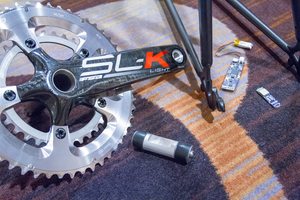
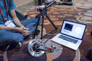
Last fall I sat down to meet with the folks behind Ashton Instruments, an up and coming power meter company. At the time we sat down in a random hallway at the Mandalay Bay convention center on horrible looking carpet with equally bad lighting. They had brought with them some early models of their unit, as well as a host of data and explanations. Here’s a few photos from that encounter:
I never ended up writing about them, partly because the photos came out horribly – but mostly because I didn’t feel like it had enough grounding in reality yet. I meet with prospective power meter companies quite frequently – all of which you’ve never heard of it (and most want to keep it that way for a while). But in their case I felt like they needed to go back and spend the winter to prove what they had. And that they did.
This past Friday I met with them again, as the last company on my US road trip last week, just before I headed out to the airport. And this time, they definitely proved they were on the right track. Of course, it’s still early in development – but definitely worthy of talking about now.
The Device:
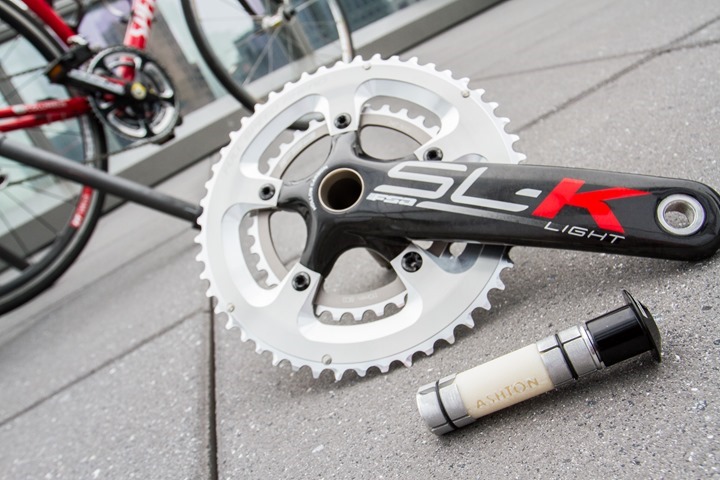
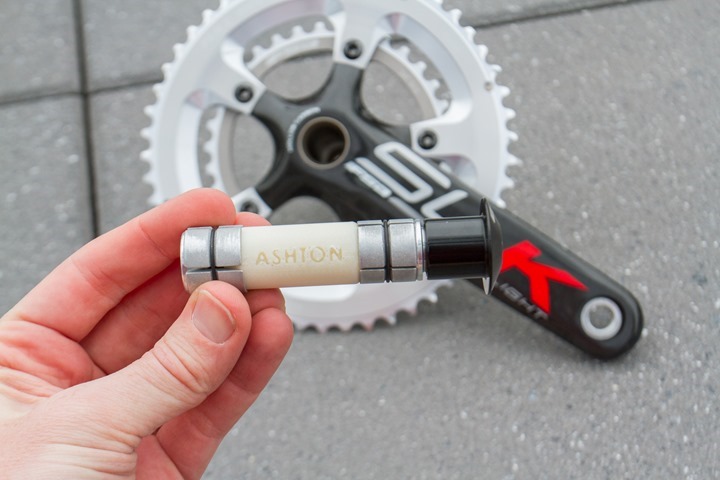
Their power meter is pretty much unlike anything else currently on the market. Though, there are elements of it that can be seen in products long since passed (i.e. Ergomo). The nameless unit (seen above) slides into your bottom bracket. The bottom bracket is the hole at the bottom of your bike that allows the crank to connect on both sides.
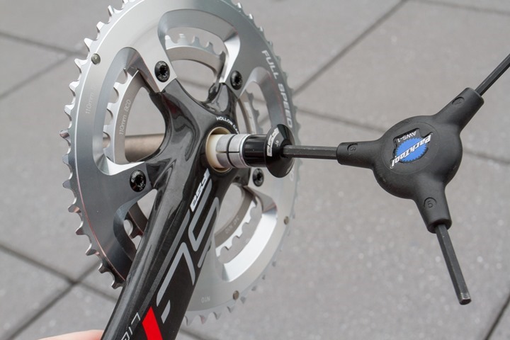
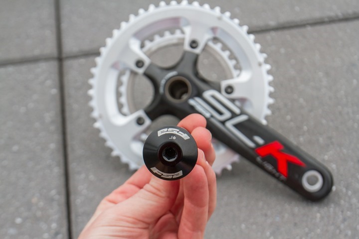
In this case, it simply screws in by slightly expanding the cap when you tighten the bolt:
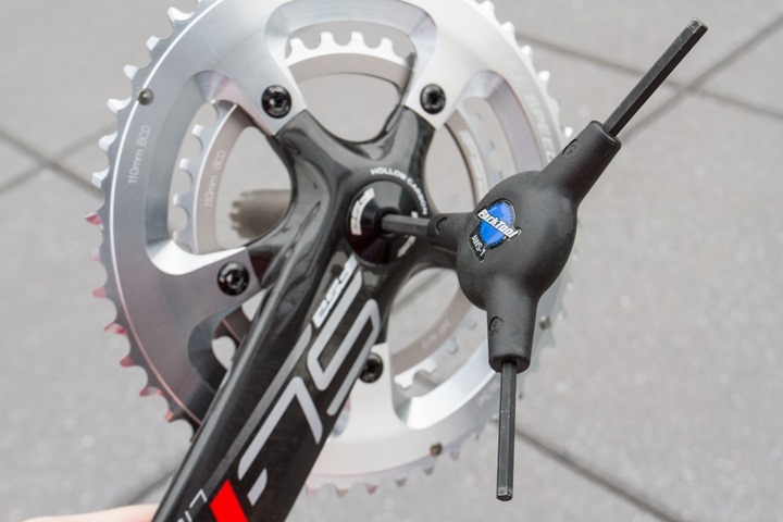
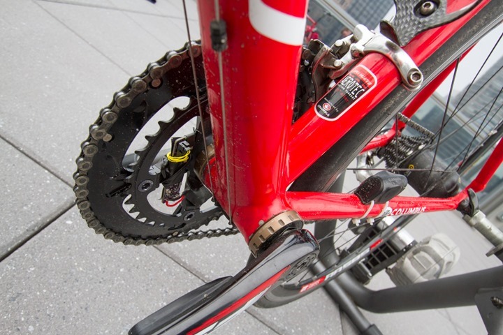
A secondary bolt would also tighten from the other side in the next prototype version, to ensure it stays put. In the meantime, you can see it from the other side, inside:
This design allows the unit to be easily installed by basically anyone. Essentially, if you can install a water bottle cage, you can install this power meter. I can’t think of another product on the market that has that level of simplicity – except the PowerTap in a pre-configured wheel (where the hard part is done for you).
Oh..and one thing: There are no strain gauges. Yup, you read that right – a direct force power meter without otherwise industry norm strain gauges.
So how does it work? Well, the easiest way to think about it is that as the unit slides inside it measures rotational twist in two places within the crank spindle. By knowing how much rotational twist you’re putting out it can determine how much force you’re generating and thus determine power.
There are some limitations to this scheme however. Namely that it only measures one-leg (left in this case). So it’s sorta like a Stages power meter being one-sided. For some budgets/expectations that won’t be an issue. For others, it may be a show stopper. Really up to individual situations.
The unit will eventually dual broadcast ANT+ and Bluetooth Smart, though neither were enabled on the prototype unit they had with them. Instead, it was just recording it internally.
Here’s a quick video I put together looking at all the pieces and where they go:

With that out of the way, let’s get onto the road.
Some short test rides:
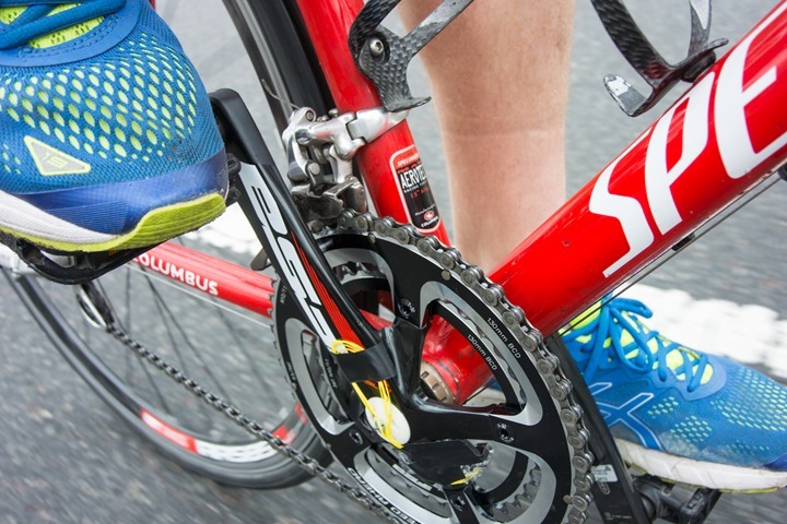
We had a bit of time in the afternoon during my trip to NYC, so we set about to do two test rides on prototypes. The first was outside at Central Park. Being an early stage prototype, they protected the unit with plastic wrap (seen to the side)– mostly because of the wet road conditions (and probably a bit to keep the Central Park horse crap on the road out of it too).
From there I did a short loop with it. While I had cycling shoes on the trip, we didn’t think to coordinate pedals/cleats – so I just used running shoes and they had flat pedals. Perfectly functional for this basic level of testing.
Unfortunately, nothing recorded. After some troubleshooting, the unit wasn’t recording to the onboard memory (it doesn’t yet have ANT+ or Bluetooth Smart broadcasting enabled on it). So we had to swap to a second unit. That was best done at the hotel.
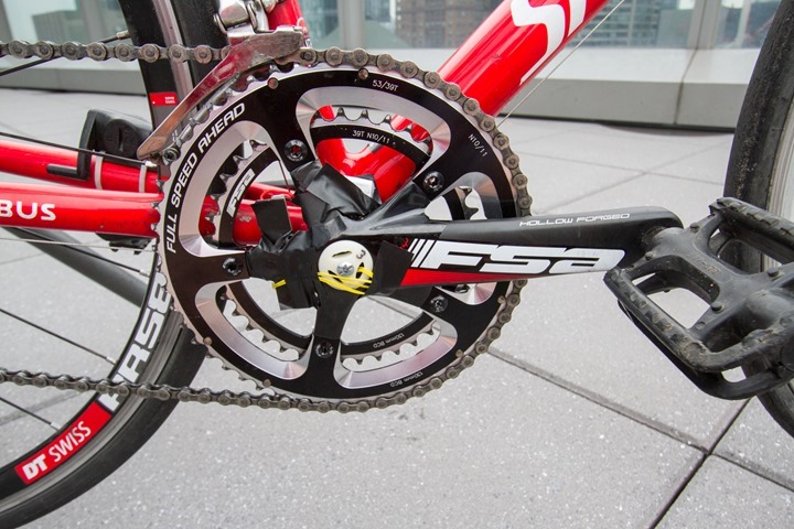
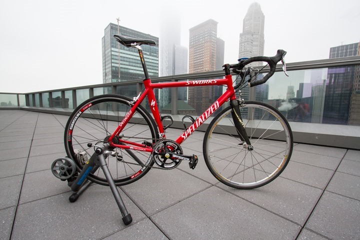
So we decided to go up to the 35th floor of the hotel on a deck outside the fitness center. It’s quickly becoming one of my favorite locales for doing product shots as there’s very rarely anyone up there. Plus, it just looks cool.
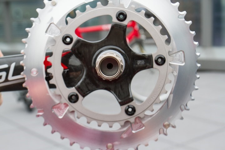
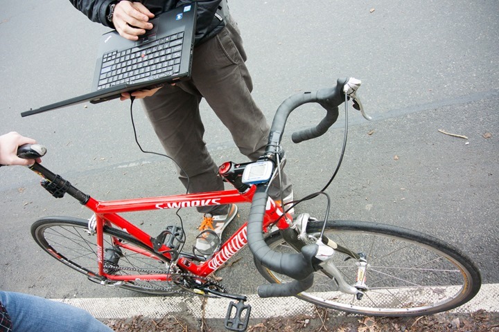
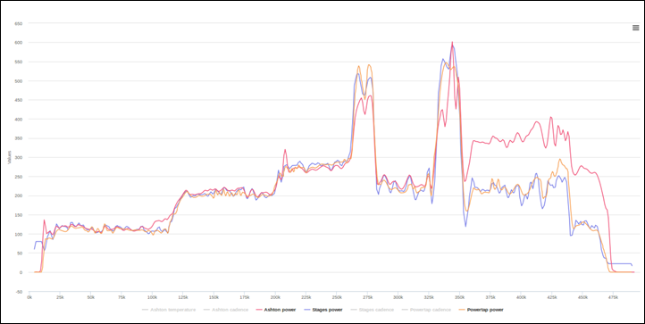
I did a short test ride on the bike starting off at lower power levels and then increasing up to about 275w before doing a few short sprints at 500-600w. The bike was outfitted with both a PowerTap as well as a Stages Power Meter. You can see the prototype aspects pretty clearly here. Well, unless you normally electrical tape your chainrings and cranks – which does admittedly add a sniff of hardcore to the scene.
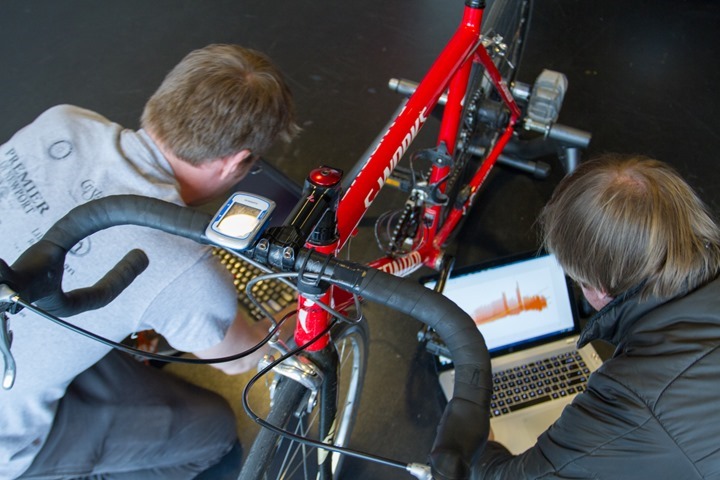
Because the data isn’t yet broadcasted in real-time, we hooked up a laptop to it to download the data, which also captured the PowerTap and Stages data.
Next, they applied a calibration offset to the data, post-ride. Normally this is done prior to riding – but that portion of the software is still on the upcoming to-do list. Below is the 5-second smoothed version showing Stages, PowerTap and them.
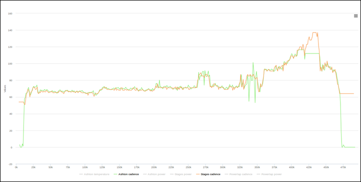
As you can see, it meshed fairly well for the first portion of the ride up until the hard/short sprints. During the sprints we see it reporting lower, which I’ll cover in a second. Then, after those sprints I go into a high-cadence section, where they track reasonably well until I get up towards the higher end.
In looking at both differences they believe they’re largely because there’s a tiny bit of slip going on at high power/cadence levels on the current prototype.
This is because the current prototype isn’t quite as snug as they want within the bottom bracket (note the electrical tape holding it in place), allowing for a tiny non-human noticeable amount of jiggle. They noted that the next prototype run should easily take care of that as it won’t be dependent on electrical tape but instead the screw system you saw earlier. Additionally, the current prototype is 3D printed, which doesn’t have quite the grip and surface of their planned units – thus contributing to the slippage.
Still, for where they are and where they know they have to go, it’s promising. At the same time, as other companies have shown – it’s easy to get 80%, 90%, or even 95% of the way there with a power meter. It’s getting from 95% to 100% that’s the toughest thing to do in this industry. Ferretting out the last little bugs can take months – or even years. Hopefully it’ll be a quick journey for them.
The Future:
Now, as is probably obvious at this point, this isn’t something you’ll be buying this year. Rather, they’re still in the device prototyping and business building stage. Right now they have functional units as seen above, but there’s still a fair bit of work to get to a retail state. Additionally, they’re still looking at gathering additional investors to get them to the finish line.
Given that, they’re targeting consumer delivery early 2016 with a sub-$500 price point. Of course, they were also aware that power meter pricing continues to drop, so they may need to re-adjust plans there depending on the market.
Still, it’s always good to see other options enter the market. And this one might just take the cake on the absolute easiest direct-force power meter out there to install. Pretty much anyone can do it, which is definitely a good starting point for a bike part.
With that – thanks for reading!
FOUND THIS POST USEFUL? SUPPORT THE SITE!
Hopefully, you found this post useful. The website is really a labor of love, so please consider becoming a DC RAINMAKER Supporter. This gets you an ad-free experience, and access to our (mostly) bi-monthly behind-the-scenes video series of “Shed Talkin’”.
Support DCRainMaker - Shop on Amazon
Otherwise, perhaps consider using the below link if shopping on Amazon. As an Amazon Associate, I earn from qualifying purchases. It doesn’t cost you anything extra, but your purchases help support this website a lot. It could simply be buying toilet paper, or this pizza oven we use and love.











Interesting. So how come only single sided? Wouldn’t the left side twist the spindle the other way?
Does it need to measure cadence (or do it anyway)?
The right (drive side) pedal power goes pedal -> crankarm -> spider -> chainring -> chain
The left pedal power goes pedal -> crankarm -> axle -> spider -> chainring -> chain
The right side doesn’t go through the axle, so any axle-based power meter would essentially measure zero for the right leg.
So this would be drive/right side power, correct? Would it be possible to combine it with a left side option like 4iiii to get two sided power?
Left side power…it’s measuring twist in the axle which originates from the left side.
Interesting/pity that you didn’t test with cleats, as wouldn’t left side upwards “pull” reduce twist on the spindle.? Seems to me there is room for material errors in that scenario
No, it wouldn’t! If you’re applying power in the forward direction (on upstroke or downstroke), you’re twisting the spindle in the same direction.
It doesn’t measure ‘up’ and ‘down’, it measures the torque and the direction of rotation it is applied to. If you pull up on the pedals you are extending that torque through more degrees of rotation & the unit would capture that. What would be really confusing for the unit is if you put it in a fixed gear.
Why would that be confusing for it? When you slow your pedal speed, it would record negative power, which makes complete sense.
A couple of typos:
Oh..and one thing: There are no straight gauges. <===strain
So we decided to go up to the 35th floor of the hotel on a desk outside the fitness center. <===deck
In looking at both differences they believe they’re largely because there’s a tiny bit of sleep going on at high power/cadence levels on the current prototype. <===slip
And one factual error. "Namely that it only measures one-leg (right in this case)" I'm certain it is measuring non-drive side power (left), since that is the only power transmitted through the bottom bracket "axle".
Grr, thanks for the typo corrections!
I’d guess left too (unless sitting on the saddle backwards :-) ).
Next time Ray you should totally set the bike up on a desk on the deck outside the fitness centre as a little inside joke for your regulars
How about battery replacement? That would probably require extracting the PM – or would there be some way to access that.
All in all, a very interesting concept – looking forward to any further updates!
It would be pretty easy to replace the battery, since it would be just popping out the unit (just two screws). Not much different than the work effort on something like a PowerTap or Power2Max. Quarq is probably the easiest as it requires zero screws, but overall most units are just a few minutes of work.
Very clever. It’s essentially a torque tube based system, like a PowerTap, except that the power meter is bearing a small part of the overall torque, rather than all of it.
Questions:
1. Will they be able to maintain accuracy over time & temperature? IF they’re not using strain gauges to measure the deflection, what are they using? Would be interesting to know their expectations on accuracy,
2. Each type of crank will twist a different amount, and the manufacturing variations with each crank vendor’s model mean that each individual specimen will twist a different amount. That means the user will need to calibrate on installation, against a known good reference. I suspect that will not prove user friendly.
3. How is wireless transmission from inside the (metal) bottom bracket going to work? Is there a good enough radio path from there to the head unit? May need an antenna sticking out from the centre of the crank.
Hi flobble, great questions!
1. It will be very accurate, meeting the current standards of direct force power meters, and we are implementing temperature compensation to maintain accuracy. As for the sensor, we’re using robust solid-state components which measure the spindle’s twist.
2. Yup, the user will calibrate on installation. We know that user-friendly installation and calibration is one of the most important aspects of our power meter and we’re fine-tuning a very simple calibration procedure.
3. We’ve successfully tested radio modules down the spindle, but yes, antenna placement is important and we will be doing further extensive testing as we continue the product development.
It’d be awesome if there was some mechanism for saving a calibration! That way if you’re switching bikes often, you don’t have to calibrate every time. Of course, this would only be if testing confirms that calibration is not significantly changed simply by the act of installation.
If it doesn’t use strain gauges, what does it use ? IIRC Ergomo used light (lasers), but that meant it used a lot of battery power (which was in the headunit as it was fully wired)
I can see this attachment method working for FSA cranks or SRAM, but campag (and specialized) spindles attach together in the middle and shimano are only open on one end (before you put the cap on). How do they plan fitting onto those cranks ?
Our first generation power meter is designed for crank spindles that are open at both ends like many FSA and SRAM options. As we’re able to further shrink the form factor in later generations, we think there are some creative ways to make an insert type power meter compatible with most crank designs.
What are they using, if not strain gauges?
Why not use strain gauges – a proven and cheap technology?
Hi Ryan,
We’re using solid-state sensor components which measure the spindle’s twist.
Cost is actually one of the main reasons we decided not to go with strain gauges. Even though our raw sensor components are already somewhat cheaper than strain gauges, it’s manufacturing advantages that really make the difference. There is an interesting BikeRadar Article that looks into this, if you’re interested.
Another advantage of using solid-state components is their robustness, an area where strain gauges sometimes struggle.
As an electrical engineer, this really intrigues me. How much detail can you give without going into trade secret type stuff?
How many sensors are measuring the twist?
If they aren’t measuring strain, are they measuring rotational displacement?
Is it actually measured in a manner similar to a strain gauge (bridge circuit + amplifier + A/D)?
How often are you sampling the torque?
How often are you sampling angular velocity?
The last two will help head off the inevitable questions about using this on non-round chain rings.
Is it QTC material based?
(such as: link to peratech.com )
Or perhaps a MEMS device.
If I were to hazard a guess I’d say a piezoelectric.
This could be the one.
How easy/quick would it be to swap it between bikes?
What is their “thing” that they are going to bring to the table over proven models on the market? Stages & Garmin Vector are pretty easy to install, but this will beat them on price (for now). Competition is great and time will tell I guess.
I’d agree with Flobble below.
The key/biggest thing (aside from price), is that it’s easy for anyone to install. If you watch the video, you’ll see how silly easy it is. Anyone who can install a water bottle cage can install this. The same (unfortunately) can’t be said for Vector or Stages (for the vast majority of the bike population).
Assuming accuracy, reliability etc end up as required, then I can think of three:
1. Installation and removal with a standard hex key (vs torque wrench) would be good.
2. If the calibration didn’t need to be repeated each time, Bluetooth would allow connectivity with a smartphone app so you could say “you’re now in my TT bike, here’s your calibration” or “you’re now in my road bike, here’s your calibration” or “you’re now in my mountain bike, here’s your calibration”
3. Much greater independence from crank type, pedal type, wheel type. None of the existing solutions can really provide that today.
I’m really excited about all the powermeter competition that seems to be coming. Its something I really want to add to my training, especially since I use a trainer a lot, but the current cost I just can’t justify.
Can there be more than $50 worth of parts in the Stages or 4iiii Precision Power Meters. Seems to me the $100 Price level can’t be too far away ..!!
How about Campagnolo Over-torque and Power-torque?? I believe they have a 1 piece spindle
Good morning, when is there bottom bracket with 2 screws of compression?
Screws of the sensor would replace them?
To everyone who thinks that the drive side doesn’t exert force on the spindle – if that was true, the NDS crank wouldn’t move when you pedalled one-legged.
You are all welcome to experiment, but I’d recommend googling “Newtons Third Law” instead
With the proliferation of one sided power meters there is a new need for possible addition to tracking options in head units to allow for right/left leg imbalances. In my case, I have a Quark on my road bike that I have been using for over a year. It shows that I have a 5% to 10% difference between legs. I have ordered a 4iiii meter for use with my mountain bike which will be installed only on my left crank. So I know that when installed, my mountain bike will probably read low when compared to my road bike.
It would be nice if I could somehow set up my Garmin Edge 810 to adjust my power measurements for when riding the mountain bike to read about 7% high so that it will correlate more closely with my road bike readings. As it is, I do spin classes once or twice a week on bikes that use a left sided Stages manufactured power meter and I have to always do a mental adjustment to the power readings.
The biggest issue here is when all this data goes into Sporttracks Training Load where it is best to have some consistency between different bike power measurements for you overall load tracking to make sense.
This would be a nice update to Garmin bike computers.
Since it is measuring rotational twist wont using clip ins lower the power reading if pulling up on one leg while pushing down on the other?
I think that could be a real issue – I just can’t see how that won’t reduce (or in an extreme case eliminate) spindle twist
It will work just fine. In the same way that any of the left-crank-only designs work just fine. From the pedal spindle to the chainrings, it’s a (mostly) rigid unit. All of it deflects, just in a different way/different amount according to geometry and material.
Plus:
(a) there is good evidence that pulling up on the pedal doesn’t happen much. It’s mostly just ‘unweighting’ to varying degrees. But that doesn’t matter because..
(b) single sided pedal meters assume that pedal action is symmetrical, so any forces from the “lazy” pedal occur apply equally to both sides. If the drive side foot was pulling up, and ‘reducing’ the measurement on the non-drive side, then 180 degrees later, the non-drive side would be pulling up, and this would be measurable, so it can be handled appropriately.
If you accept the assumption of symmetry, it’s really a non-issue.
If anyone is convinced that a single side power meter isn’t good enough because of left/right asymmetry, then they buy one that is dual sided, is in the spider, or is in the wheel. Or learn to pedal in a symmetric way.
If Bill is still around, I’d appreciate some clarification.
The article says the device measures rotational twist. Of what? Of the device? How is the device anchored to the actual drive mechanism of the bike…isn’t slippage a major problem?
If I align my crank arms horizontally, and stand on my pedals (thus not going anywhere), it seems like that will produce maximum twisting of anything mounted in the bottom bracket (one pedal is trying to go fowards, the other backwards).
If I pedal just with the left leg, there is twisting between the left crank arm and the spider, since the chain is making it hard for the spider to turn. It sounds like that twist is what you’re measuring?
What if, as others have pointed out, I pull up with my right leg at the same time? I’m reducing the twist AND putting out more power. It seems like that couldn’t just be ignored.
Never mind, I get it.
The device measures how much _additional_ force your left leg is contributing to the chain ring/spider, beyond what your right leg is doing. If your left leg wants to move the spider faster than the right leg is doing already, you’ll get twist. That means your left leg is applying force to the drivetrain. Assume left and right are equal and now you have total power. Pulling up is handled by the fact that your left leg is contributing power (And twist) on the upstroke and downstroke. Again, assume symmetry and now you have total power for both legs.
Looks like they are going to be a bit late to the market seeing that Rotor just launched something very similar: link to bikeradar.com
Any plans for a review of that?
Ask and you shall receive: link to dcrainmaker.com
Aside from ease of installation, this finaly looks like something that can be easily swapped around between roadbikes and mountainbikes! If so, I want it!
I just checked out the Ashton website and am very impressed that they had recently won several awards (2014 MIT 100K Semi-Finalist, 2014 MIT GFSA Alumni, 2014 MassChallenge Finalist and $50K Gold Award Winner). It could likely be more than a year to get their product to market. Ashton has a lot of hurdles and challenges to get to the next level.
Seeing the third hand in the Video freaked me out :-)
Great write up as usual.
Just wondering if you have any inside updates about product release or availability from Ashton? Their website never seems to change, and I’ve been really excited about this product for… to long now. ?
-Guillermo
Looks like they are out, like Brim Brothers.
No updates for ~2 years and website has been taken down http://www.ashtoninstruments.com